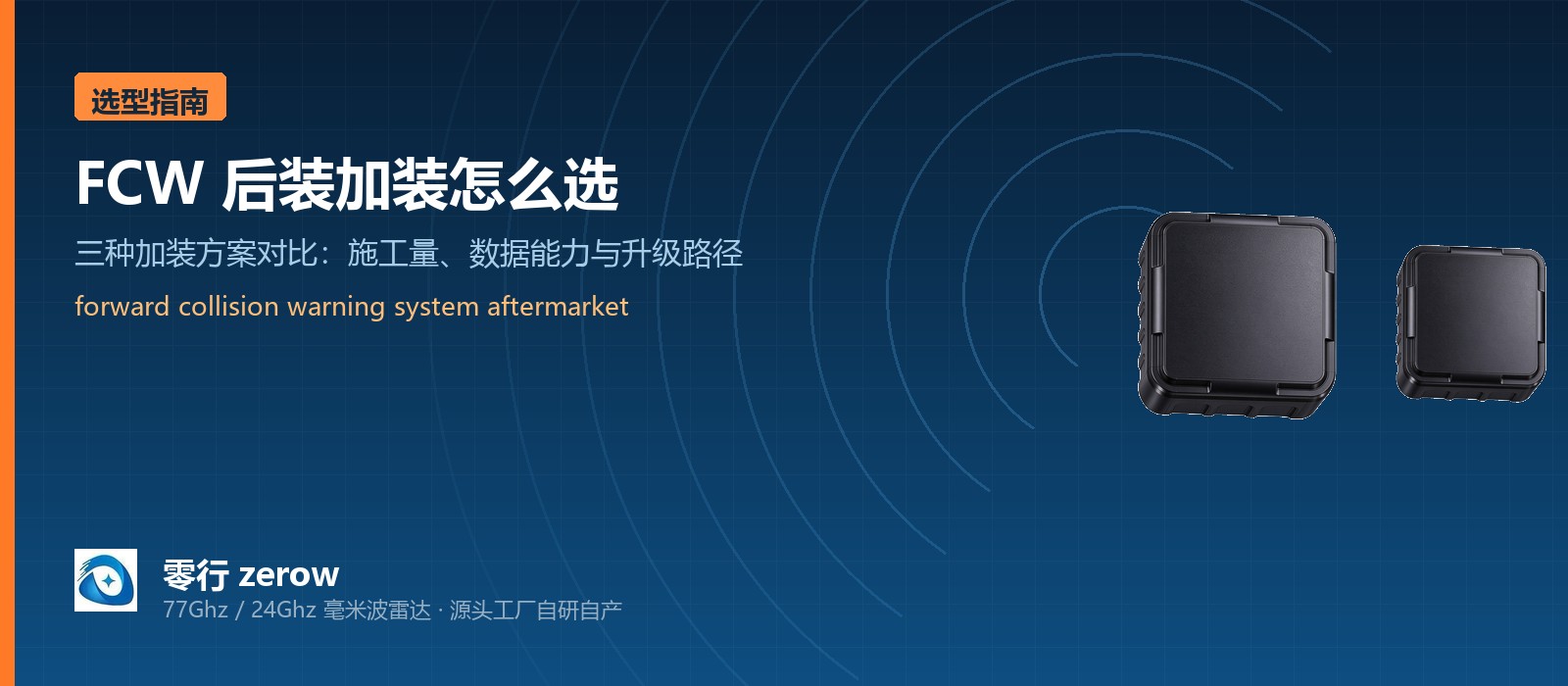
When a fleet asks for a forward collision warning system aftermarket, the hard part is rarely choosing the sensor. It is deciding how far up the stack the alarm should travel. With the same radar, a different wiring approach changes the installation workload, the data capability and the upgrade path completely. This article splits aftermarket fit-up into three workable options and compares them on installation complexity, alarm output and data capability, so you can match the right one to your fleet condition and budget and pick up a forward collision warning system aftermarket that is actually installable.
What aftermarket fit-up is actually up against
Forward collision warning on a passenger car is factory calibrated. Nothing has to be decided at fit-out time. The aftermarket is a different problem, because a truck that is already in service has to add FCW while usually meeting all of the following.
- Existing vehicles have no reserved mounting point, cable route or supply tap for a sensor, so the solution has to work on the vehicle as it stands.
- Fleets vary enormously: old diesel tippers with plastic or fibreglass bumpers sit alongside newer trucks with a central screen and T-Box, and some need front and side coverage at once.
- The modification window is short. Usually only a handful of vehicles can be done at a time, so the first-phase installation cycle has to be compressed.
- The alarm has to reach the driver for real: a beacon, a buzzer, a horn, or a message on a screen. Which layer it lands on decides the hardware.
With those constraints in view, the differences between aftermarket options become easy to read. They are essentially decided by two questions: do you connect to the vehicle bus, and do you push the target data into your own terminal.
Why aftermarket fit-up leans on millimeter wave radar
This is not because LiDAR is bad. It is because three constraints of the retrofit scenario happen to point the same way.
- Availability in bad weather: 77GHz radio waves pass through rain, fog and dust far better than near-infrared laser. Construction vehicles run every day, and the sensor cannot drop out exactly when it is needed.
- Response speed: millimeter wave radar outputs range and relative speed within a single frame. K120 runs a 100ms frame period (10Hz), and its relative speed accuracy is in the range that can feed a TTC calculation directly - and TTC is the core variable in forward warning.
- Installation effort: target-level output carries very little data and needs no domain-controller class compute. Both K120 and K60 provide CAN 2.0B plus three high-level alarm outputs and one DI enable input, which means the alarm can work with no connection to the vehicle bus at all, or the radar can go on the bus and push target data up.
In other words: choosing millimeter wave radar is only the first step. The wiring decision is what shapes the project.
Three retrofit options compared
By whether the vehicle bus is used and where the alarm lands, aftermarket fit-up splits into three shapes. They differ hugely in installation workload, commissioning and the upgrade path ahead.
- Option A, simplest non-invasive retrofit: no connection to the vehicle CAN at all. The radar drives a beacon, buzzer or horn directly through its three high-level outputs. Lowest installation effort and the fastest first-phase validation.
- Option B, data-level retrofit: the radar joins the CAN 2.0B bus (500K or 250K), and your own T-Box or central display reads target position and speed for secondary presentation. Data reaches the platform, so fleet-level statistics and alarm logging become possible.
- Option C, multi-radar network: several radars share one CAN bus and are distinguished by radar ID, so a forward K120 can be extended with K60 units covering mid-range and side blind spots. Suited to multi-zone coverage requirements.
The pattern in selection is straightforward. If the first-phase goal is to get the vehicle alarming at all, use Option A. Once the fleet scales and you need target data in your own terminal or display, move up to Option B. Multi-radar networking is only justified when multi-zone coverage is genuinely required.
Option A: the simplest non-invasive retrofit
The defining feature here is that the vehicle bus is left completely untouched, which compresses every other part of the work.
- Power: tap ACC or a fuse box. Note that diesel trucks commonly run 24V systems, while K120 and K60 accept 9 to 16V DC, so a DC-DC converter is required and connecting straight to the battery will not work.
- Signal: no connection to the vehicle CAN at all. The radar drives external audible and visual devices through its three high-level alarm outputs (IO1, IO2, IO3), with one DI acting as enable.
- Workload: bracket, power tap, three alarm wires and one enable wire. No protocol integration.
- Commissioning: zones, alarm logic and enable conditions are set through the UART/USB host tool, which one engineer can complete.
The value of this option is that it minimises the cost of learning. Prove the alarm logic on two or three vehicles under real fleet conditions first, then decide whether the data-level option is worth moving to.
Option B: data-level retrofit for fleets with a screen or T-Box
When a fleet already runs its own terminal, the alarm should not just be a horn. It should be a record on that terminal, carrying target information. That is what Option B is for.
- Connection: CAN 2.0B at 500K or 250K, with the radar publishing target lists in standard frames.
Option A: the simplest non-invasive retrofit (the usual fcw aftermarket kit truck starting point)
- Protocol support: we supply the zerow obstacle radar CAN communication protocol document with parsing references for direct integration with an existing platform.
- Additional benefit: once target data reaches the platform you can log false positives, missed-response events and build event history - none of which is possible with a bare alarm output.
Option B is the end state for most fleets with digital fleet management, but it assumes the vehicle already has a terminal that can parse CAN.
Option C: multi-radar networking
When one vehicle needs more than forward long-range warning - forward plus mid-range plus side coverage - several radars have to share one bus and be managed together.
- Topology: multiple radars on the same CAN bus, distinguished by radar ID, with each radar mapped to its own zone alarm outputs.
- Expansion: a forward K120 can be extended with K60 units covering 0.2 to 60m for mid-range and side blind spots.
- Configuration requirement: radar count, ID assignment and zone mapping must be defined consistently, and we supply the matching configuration document and host tool.
One caveat worth stating plainly: cost and complexity of Option C rise roughly in line with radar count, and the payoff only exists if multi-zone coverage is genuinely needed. For forward FCW alone, Option A or B is more economical.
Four structural advantages for retrofit work
From an engineering standpoint, millimeter wave radar has several advantages that decide whether a retrofit project can actually be delivered on schedule.
- Small and light: modular construction fits behind the front bumper or at the front of the engine bay, with no need to reshape bodywork for the sensor.
- Environmentally tough: IP67 and -40 to +85 degrees Celsius, so it can sit exposed at the front of the engine bay or behind a bumper.
- Installation and commissioning decouple: targets, alarm logic and enable conditions are set through the host tool, so mechanical fitting and parameter setup can be done by different people at different times.
- Application-layer support: application-layer warning logic and protocol documentation are available, so you do not need to build a radar algorithm team.
Together these four decide the part that actually matters in a retrofit project - not the numbers on a datasheet, but how many days the installation schedule compresses to.
Six things to confirm before quoting
The following six items determine how the alarm logic is configured, where the bracket goes and which option fits. Settle them before pricing.
- Vehicle list and front-end photos: voltage systems and front-end structures vary significantly between models.
- Front bumper material: plastic or fibreglass can take a concealed install; a metal bumper needs a different mounting point.
- Whether the front end has large chromed or highly reflective surfaces: these cause multipath reflection and introduce unwanted phantom targets.
- Target speed band and typical operating speed: these set the TTC threshold and the trigger distance for each of the three zones.
- Preferred alarm form: buzzer, LED beacon, horn or an on-screen message - this decides the IO versus CAN trade-off.
- First-phase vehicle count: this decides whether parameters are tuned per vehicle or whether we supply batch configuration and consistency checks.
Once these six are settled, the installation position proposal and the configuration parameter sheet can be produced.
A suggested path forward
Four stages, each with a defined deliverable, and no paper-only exercises.
- Step 1, align on requirements, about 1 week: confirm the six items above and produce the installation position proposal and configuration parameter sheet.
- Step 2, sample vehicle testing, 2 to 4 weeks: fit 1 to 2 vehicles and run them in real operating conditions, recording false positives, misses and behaviour in bad weather.
- Step 3, small batch validation, 1 to 2 months: fit 3 to 10 vehicles over a full duty cycle and produce a validation report.
- Step 4, volume approval: lock the BOM and technical agreement against the measured data and move to series supply.
One recommendation that is easy to overlook but matters: write adverse-condition testing explicitly into the Step 2 acceptance criteria. Performance in rain, fog and at night is exactly where millimeter wave radar and LiDAR separate. Without it in the acceptance criteria, the project drifts into argument about paper parameters later.
zerow's K120 (0.4 to 120m, range accuracy within plus or minus 0.4m, 100ms frame period at 10Hz, up to 32 targets per frame, three-zone graded warning with a TTC risk gate) and K60 (0.2 to 60m, range accuracy within plus or minus 0.2m, 50ms frame period at 20Hz, up to 64 targets per frame, three-zone graded warning) both use the Siversemi Cheetah4401 2T4R radio front end with an Ingenic X2100 processor. Both are IP67 rated, operate from -40 to +85 degrees Celsius, accept 9 to 16V DC, and provide CAN 2.0B plus UART/USB, three high-level alarm outputs and one DI enable input. Radar module, PCBA and complete unit are all available, with OEM and ODM support. Get in touch for the full datasheet and a selection recommendation.